You are here: Building the Model: General Elements > Locations > Capacities and Units > Multi-Capacity, Multi-Unit, and Multiple Locations
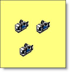
Sometimes it can be unclear whether to use multi-capacity, multi-unit, or multiple locations when defining parallel workstations. Suppose, for example, we have three parallel stations, each performing the same operation as shown below. There are three possibilities for defining the machines: (1) as a multi-capacity location, (2) as a multi-unit location, or (3) as multiple locations. The method you choose to define the locations depends on your application.
For many situations modeling parallel stations as a multi-capacity location works fine. By placing an additional graphic for each station, both the logic and visual effects of having parallel stations can be achieved. However, you should use a multi-unit location instead of a multi-capacity location when any of the following situations exist:
• Individual units have independent downtimes.
• It is important to collect individual statistics on each unit.
• It is important, for visual effect, to see entities select individual units by a routing rule other than First Available (e.g., By Turn, Fewest Entries, Longest Empty, etc.).
• It is important, for visual effect, to have a status light assigned to each unit.
In some situations, it may even be desirable to model multi-unit locations as totally separate locations. Multiple locations should be used instead of multi-unit locations when:
• A path network is defined but each location must interface with a different node on the network.
• Different units have different processing times.
• The input for each unit comes from different sources.
• The routing is different for each unit.
To create a multi-unit location, enter a number greater than one as the number of units for a location. A corresponding number of locations will be copied below the multi-unit location record in the Location edit table, each with a numeric extension designating the unit number of that location. Successive graphics, representing individual units will be drawn to the right of the original location, but may be moved normally.
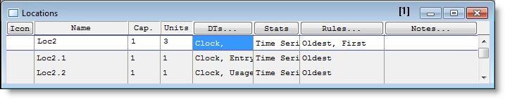
The original location record becomes the prototype for the unit records. Each unit will have the prototype's characteristics unless the individual unit's characteristics are changed. In the table below, each unit of the location has a clock-based downtime defined because the parent location, Loc2, was assigned a clock-based downtime. However, Loc2.1 has an additional entry-based downtime and Loc2.2 has an additional usage-based downtime. Any other characteristic, including the icon, can be changed as if the unit were an independent location.
If the number of units is changed, the individual unit location records are automatically created or destroyed accordingly.
Individual units of a multi-unit location can be selected to process an entity according to the Selecting Incoming Entities option in the Rules dialog box. (See the discussion regarding the Rules dialog box later in this section.)
In the output report, scheduled hours for the parent location will be the sum of the scheduled hours for the individual units.
Please note
Multi-Unit notes:
1. It is not possible to create a path network to interface with each unit of a multi-unit location. You must define the locations individually and use multiple locations as discussed above.
2. It is not possible to route an entity to a specific unit of a multi-unit location. For example, typing Loc2.3 in the destination field of the Routing edit table is not allowed.